Tag Archives for " analysis "

Monitoring WebRTC apps just got a lot more powerful

As we head into 2019, I noticed that we haven’t published much around here. We doubled down on helping our customers (and doing some case studies with them) and on polishing our service.

In the recent round of updates, we added 3 very powerful capabilities to testRTC that can be used in both monitoring and testing, but make a lot of sense for our monitoring customers. How do I know that? Because the requests for these features came from our customers.

Here’s what got added in this round:

1. HAR files support

HAR stands for HTTP Archive. It is a file format that browsers and certain viewer apps support. When your web application gets loaded by a browser, all network activity gets logged by the browser and can be collected by a HAR file that can later be retrieved and viewed.

Our focus has always been WebRTC, so collecting network traffic information that isn’t directly WebRTC wasn’t on our minds. This changed once customers approached us asking for assistance with sporadic failures that were hard to reproduce and hard to debug.

In one case, a customer knew there’s a 502 failure due to the failure screenshot we generate, but it wasn’t that easy to know which of his servers and services was the one causing it. Since the failure is sporadic and isn’t consistent, he couldn’t get to the bottom of it. By using the HAR files we can collect in his monitor, the moment this happens again, he will have all the network traces for that 502, making it easier to catch.

Here’s how to enable it on your tests/monitors:

Go to the test editor, and add to the run options the term #har-file


Once there and the test/monitor runs next, it will create a new file that can be found under the Logs tab of the test results for each probe:

We don’t handle visualization for HAR files for the moment, but you can download the file and place it on a visual tool.

I use netlog-viewer.

Here’s what I got for appr.tc:

2. Retry mechanism

There are times when tests just fail with no good reason. This is doubly true for automating web UI, where minor time differences may cause problems or when user behavior is just different than an automated machine. A good example is a person who couldn’t login – usually, he will simply retry.

When running a monitor, you don’t want these nagging failures to bog you down. What you are most interested in isn’t bug squashing (at least not everyone) it is uptime and quality of service. Towards that goal, we’ve added another run option – #try

If you add this run option to your monitor, with a number next to it, that monitor will retry the test a few more times before reporting a failure. #try:3 for example, will retry twice the same script before reporting a failure.

What you’ll get in your monitor might be something similar to this:

The test reports a success, and the reason indicates a few times where it got retried.

3. Scoring of monitor runs

We’ve started to add a scoring system to our tests. This feature is still open only to select customers (want to join in on the fun? Contact us)

This scoring system places a test based on its media metrics collected on a scale of 0-10. We decided not to go for the traditional MOS scoring of 1-5 because of various reasons:

  1. MOS scoring is usually done for voice, and we want to score video
  2. We score the whole tests and not only a single channel
  3. MOS is rather subjective, and while we are too, we didn’t want to get into the conversation of “is 3.2 a good result or a bad result?”

The idea behind our scores is not to look at the value as good or bad (we can’t tell either) but rather look at the difference between the value across probes or across runs.

Two examples of where it is useful:

  1. You want to run a large stress test. Baseline it with 1-2 probes. See the score value. Now run with 100 or 1000 probes. Check the score value. Did it drop?
  2. You are running a monitor. Did today’s runs fair better than yesterday’s runs? Worse? The same?

What we did in this release was add the score value to the webhook. This means you can now run your monitors and collect the media quality scores we create and then trendline them in your own monitoring service – splunk, elastic search, datadog, whatever.

Here’s how the webhook looks like now:

The rank field in the webhook indicates the media score of this session. In this case, it is an AppRTC test that was forced to run on simulated 3G and poor 4G networks for the users.

As with any release, a lot more got squeezed into the release. These are just the ones I wanted to share here this time.

If you are interested in a monitoring service that provides predictable synthetics WebRTC clients to run against your service, checking for uptime and quality – check us out.

24

How Many Sessions Can a Kurento Server Hold?

Here’s a question we come across quite often at testRTC.

You decided to self develop your own service. Manage your own media servers. And now that time comes to understand your ongoing costs as well as decide on the scale out scheme – at what point do you launch/spawn a new server to take up some of the load from your current media servers farm? How many users can you cram into a single media server anyway?

We decided to check just that, doing it with the help of WebRTC.ventures who worked with us on the setup.

For the purpose of these set of sizing experiments, we picked up Kurento, one of the most versatile open source media servers out there today. We selected a few key scenarios, and WebRTC.ventures installed the server and configured it for us.

We then used our testRTC probes to understand how many users can we cram on the server in each scenario.

Simple scenario sizing is one step in the process. If you are serious about your service, then check out our best practices to stress testing your WebRTC application.

Get the best practices guide

Why Kurento?

There are a couple of reasons why we picked Kurento for this one.

  1. Because many use it out there, and we’ve been helping customers understand and debug it when they needed to
  2. It is versatile. We could try multiple scenarios with it with relative ease and little programming (although that wasn’t our part of the project)
  3. It does media processing beyond just routing media. We wanted to see how this will affect the numbers, especially considering the last reason below
  4. It’s the first of a few media servers we’re going to play with, so stay with us on this one

The Scenarios

For the Kurento service, we picked up 3 different scenarios we wanted to test:

  1. 1:1 video calls. A typical doctor visitation or similar scenario, where two participants join the same session and the session gets recorded (two separate streams, one for each participant).
  2. 4-way group video calls. The classic scenario, in an MCU configuration. Kurento decodes and encodes all media streams, so we’re giving it quite a workout
  3. Live broadcast. A single person talking to a large group of viewers.

For scenarios (1) and (2) our question is how many concurrent sessions can the Kurento server hold.

For scenario (3) our question is how many viewers for a single broadcast can the Kurento server hold.

The Setup

To set things up for our test, we did the following:

  • We went for a simple AWS t2.medium machine, but quickly had to switch to a more capable machine. We ended up with a c4.2xlarge instance (8 vCPU, 15 GB RAM) on AWS
  • We had it monitored via New Relic, to be able to check the metrics (but later decided to forgo this approach and just use top with root access directly on the machine)
  • We also had an easy way to reset the Kurento server. We knew that rattling it too much between tests without a reset would affect our results. We wanted a clean slate each time we started

The machine was hosted in Amazon US-East.

testRTC probes were coming in from a different cloud vendor, East and West US locations.

We didn’t do any TURN related stuff – so our browser traffic hit the Kurento server directly and over UDP.

The Process

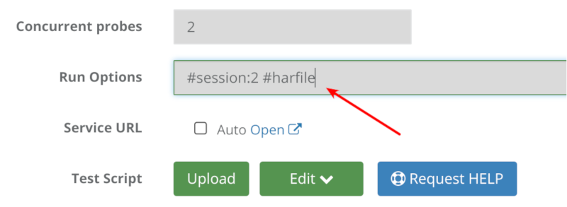
For each scenario, we’ve written a simple test script that can scale nicely.

We then executed the test script in its minimal size.

For 1:1 video calls and broadcasts we used 2 probes and for the 4-way group video call we started with 4 probes.

We ran each test for a period of 4-5 minutes, to check the stability of the media flow.

We used that as the baseline of our results and monitored to see when adding more probes caused the media metrics to start faltering.

1:1 Video Calls

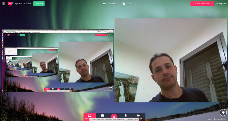
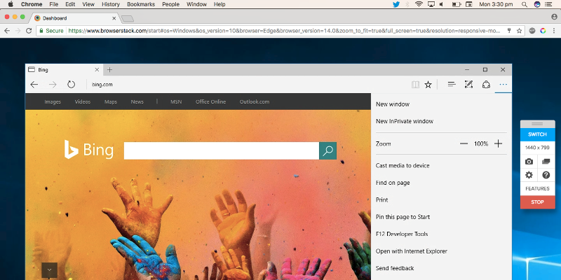
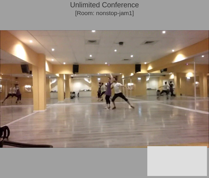
The above screenshot is what you’ll see if you participated in these sessions. There’s a picture in picture view of the session, where the full screen area is the remote incoming video and the smaller window holds our local view.

Baseline

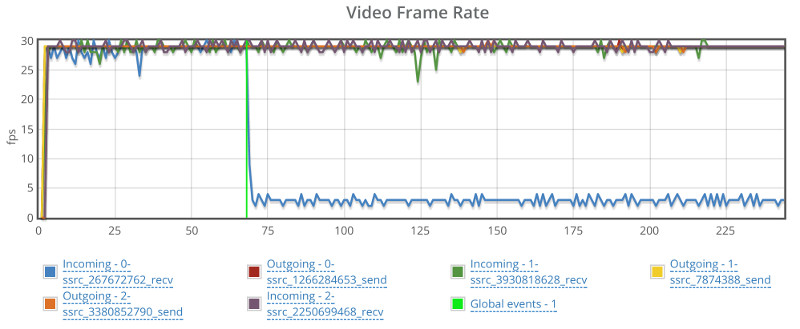
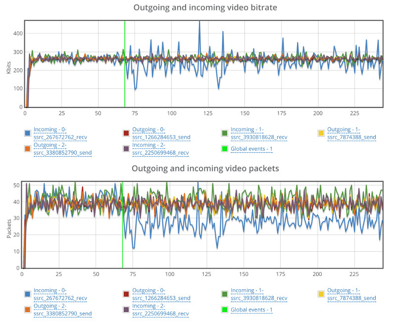
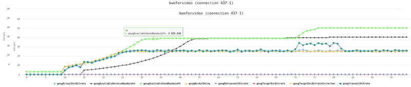
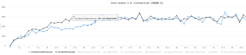
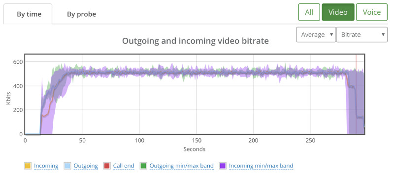
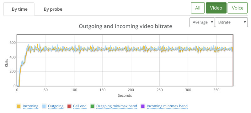
Kurento’s basic configuration limits bitrate of calls to around 500kbps. This can be seen from running a single session in our high level chart:

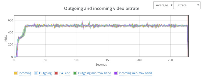
And here’s the stats on the channels of one of the two probes in this baseline test run:

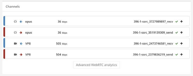
Now that we have our baseline, it was time to scale things up.

30 Probes (=15 sessions)

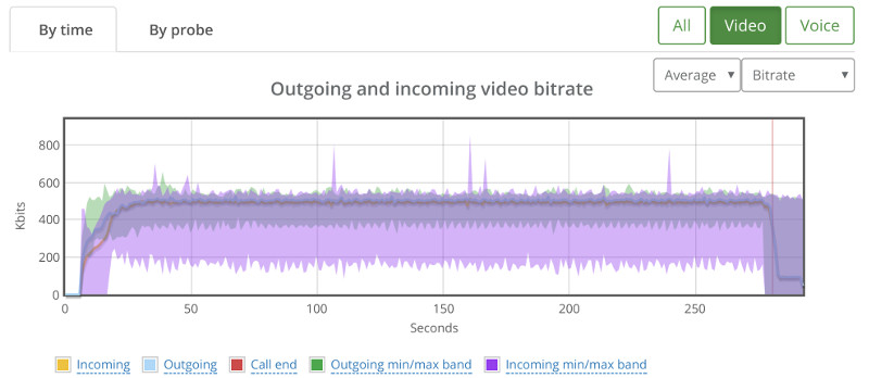
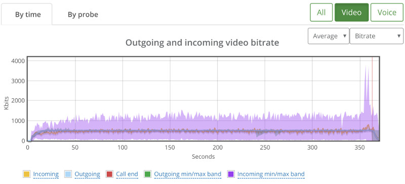
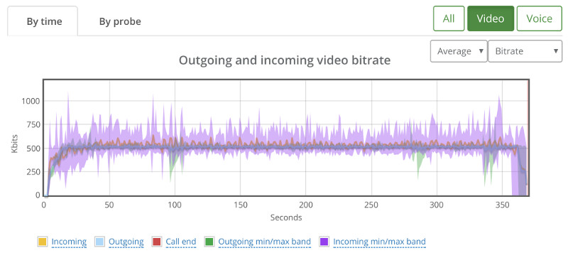
When we went up to 30 probes, running in 15 parallel 1:1 video sessions, we ended up with this graph:

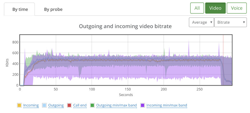
While the average bitrate is still around 500kbps, we can see that the min/max bands are not as stable.

If we look at the packet loss graph, things aren’t happy (the baseline had no packet losses):

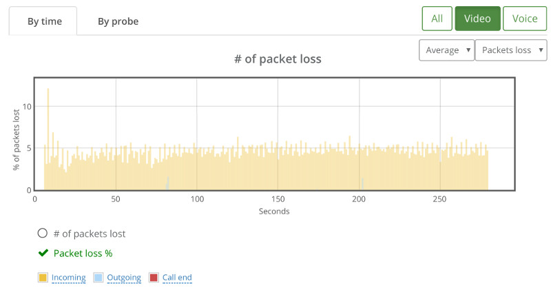
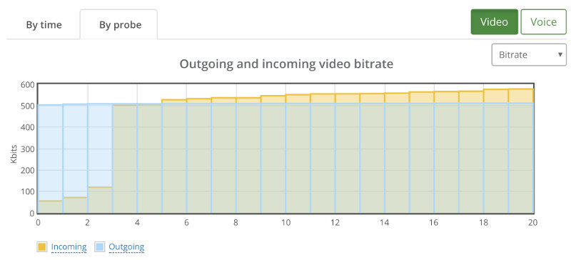
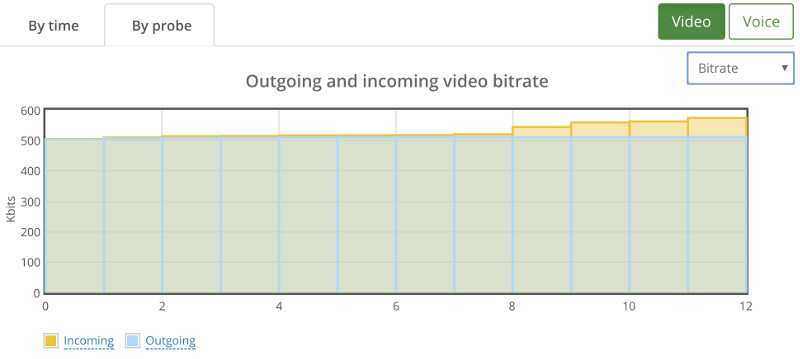
This is where we went for the “By probe” tab, looking at individual bitrates across the probes:

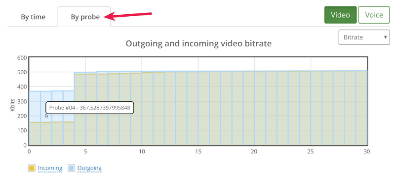
What we can see immediately is that 4 probes out of 30 didn’t get the full attention of the Kurento media server – they got to send and receive less than 500kbps.

If we switch to the packet loss by probe, we see this:

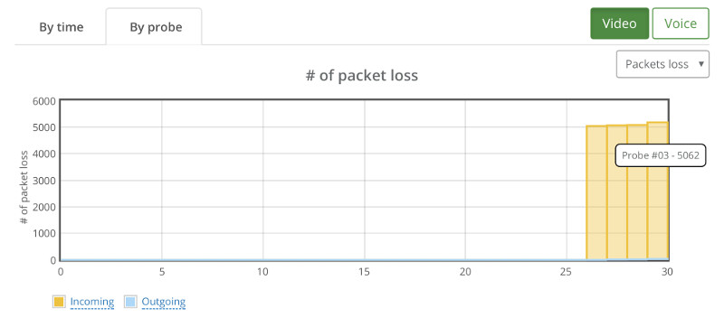
A couple of things that come to mind:

  1. Kurento degrades quality to specific sessions and not across the board. Out of 30 users, 22 got the expected results, 4 had lower bitrates and another 4 had packet losses
  2. There’s correlation here. When Probe #04 exhibits reduction in bitrate, Probe #3 reports incoming packet losses

From here, we can easily go down the path of drilling down to the probes that showed issues. I won’t do it now, as there’s still a lot to cover.

22 Probes (=11 sessions)

It stands to reason then that lowering the capacity to 22 probes should give us pristine results.

Here’s what we’ve seen instead:

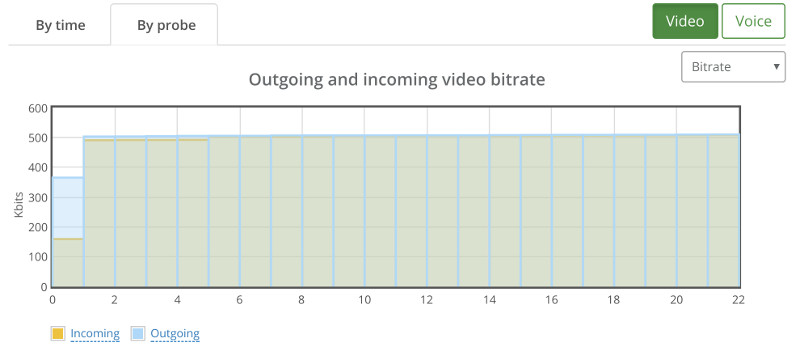
We still have that one session that goes bad.

20 or 18?

When we went down to 18 or 20 probes, things got better.

With 20 the issue is that we couldn’t really reproduce a good result at all times. Sometimes, the scenario worked, and other times, it looked like the issues we’ve seen with the 22 probes.

18 though seemed rather stable when tested a couple of times:

Depending on the service you’re offering, I’d pick 18. Or even go down to 16…

4-Way Group Video Calls

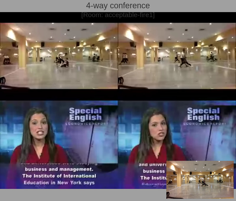
The above is a screen capture of the 4-way group video call scenario we’ve analyzed.

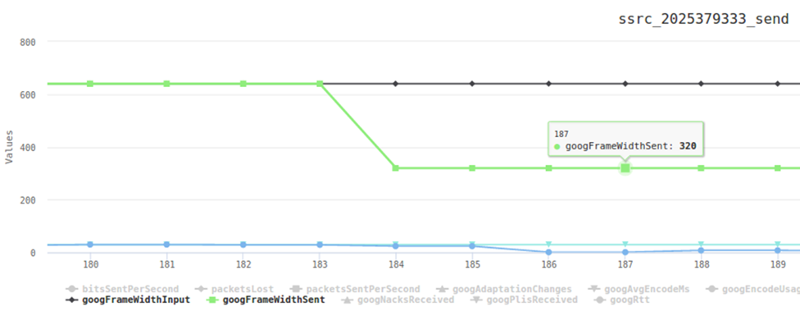
In this case, each probe (browser) sends out video at a resolution of 640×360 and receives a video resolution of 800×600.

The screenshot doesn’t show the images getting cropped, so we can assume the Kurento media server takes the following approach to its pipeline:

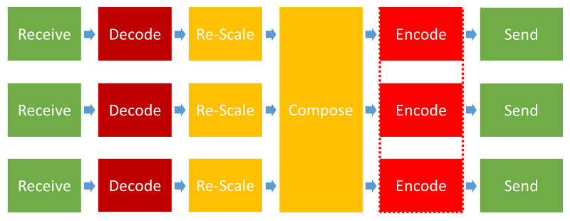
That’s lots of processing needed for each probe added, which means we can expect lower scaling for this scenario.

Baseline

Our baseline this time is going to need 4 probes.

Here’s high the high level video graph looks like:

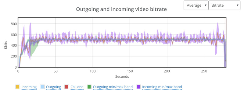
Not as stable as our 1:1 video calls, but it should do for what’s coming.

Note that each probe still has around 500kbps of video bitrate.

I’ll skip the drill down into the results of a specific probe metrics and take this as our baseline.

20 Probes (=5 sessions)

Since 1:1 video sessions didn’t go well above 20, we started there and went down.

Here’s how 20 probes look like:

Erratic.

Checking packet losses and bitrates by probe yielded similar results to the bad 1:1 sessions. Here’s the by probe bitrate graph:

Going down to 16 probes (=4 sessions) wasn’t any better:

I’ve actually looked at the bitrates and packet losses by probe, and then decided to map them out into the sessions we had:

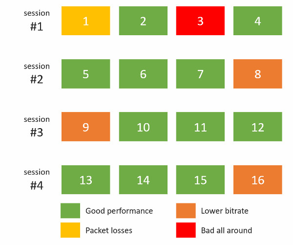
This paints a rather grim picture – all 4 sessions hosted on the Kurento server suffered in one way or another. Somehow, the bad behavior wasn’t limited to one session, but showed itself on all of them.

Down to 12 Probes (=3 sessions)

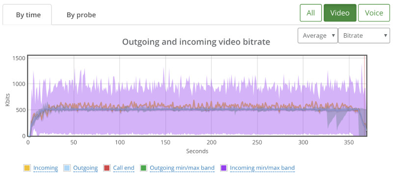
We ended up with 12 probes showing this high level bitrate graph:

It showed some sporadic packet losses that were spread across 3 different probes. The following shows the high level by probe bitrate graph:

There’s some instability in the bitrates and the packet losses which will need some further investigation, but this is probably something we can work with and try and optimize our service to run well.

Live Broadcast

The above screenshot shows what a viewer sees on a live broadcast scenario that we’ve set up using Kurento.

We’ve got multiple testRTC probes joining the same broadcast, with the first one acting as the broadcaster and the rest are just viewers.

Baseline

Our baseline this time is going to need 2 probes. A broadcaster and a viewer.

From now on, we’ll be focusing on what the viewers experience – a lot more than what happens to the broadcaster.

We’re still in the domain of 500kbps for the video channel:

One thing to remember here – outgoing media happens only for our broadcaster probe and incoming media happens for all the other probes.

30 Probe (=29 viewers)

We started with 30 probes – assuming we will fail miserably based on our previous tests, and got positively surprised:

Solid bitrate for this test.

Climbing up

We’ve then started moving up with the numbers.

50, 60 and 80 probes went really well.

Got our appetite, and jumped towards 150 probes.

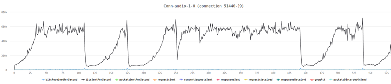
And ended up with this high level graph:

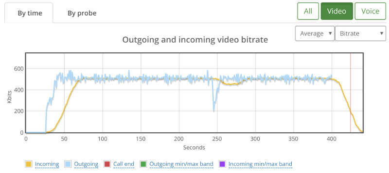
There wasn’t any packet loss to indicate why that drop with the broadcaster at around 240 seconds, so I switch to the “By probe” view.

This showed that things were starting to deteriorate somewhat:

We’re sorting the results just for this purpose – you can see there’s a slight decline in average bitrate across the probes here – something that is a lot less apparent for smaller test sizes. There was no packet loss.

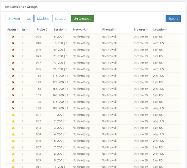
We’ve tried going upwards to 200, but then 12 probes didn’t even connect properly:

Going down to a 100 yielded some connection errors in some of the probes as well. Specifically, I saw this one:

This indicates we’ve got a wee bit of an issue here that needs to be solved before we can continue our stress tests any further. Most probably in the signaling layer of our server. It is either unstable when we place so many viewers at once against it, or just doesn’t really handle the load well enough.

Results Summary

The table below shows the various limits we’ve reached in our rounds of sizing tests:

Scenario Size
1:1 video calls 18 users in 9 parallel sessions
4-way group video calls 3 rooms of 4 users each
Live broadcast 1 broadcaster + 80-150 viewers

What did we learn?

  1. Stress testing for sizing purposes is fun. I actually enjoyed going through the results and running a couple of tests of my own (I didn’t write the scripts or run the initial tests – I delegated that to our support engineer)
  2. Different scenarios will dictate very different sizing. With more time, I’d start working out on finding the bottlenecks and optimizing them – I’m sure more can be squeezed out of a Kurento machine
  3. Once set up and written intelligently, it’s really easy to rerun the tests and change the number of probes used

Next Steps

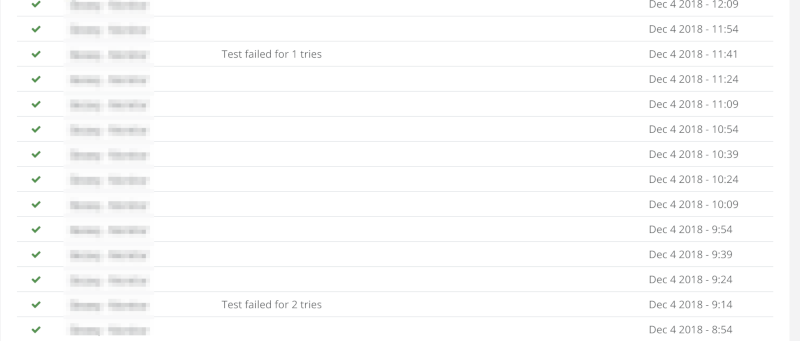
Once we got to the sweet spot in each scenario, the next thing to do would probably to run it more than once.

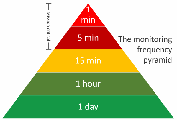
We usually setup a testRTC monitor to run once every 15 minutes to an hour for a couple of days on such a scenario, just to make sure we’re seeing stable results more than once.

Other than that, this needs to be tested under different network conditions, varying load factors, etc.

Check out our best practices for stress testing WebRTC applications. It is relevant even if you are not using testRTC

Get the best practices guide

I’d like to thank WebRTC.ventures for the assistance in setting this one up. If you are looking for a capable vendor to custom build your WebRTC application – check them out.

5

Just Landed: Automated WebRTC Screen Sharing Testing in testRTC

Well… this week we had a bit of a rough start, but we’re here. We just updated our production version of testRTC with some really cool capabilities. The time was selected to fit with the vacation schedule of everyone in this hectic summer and also because of some nagging Node.js security patch.

As always, our new release comes with too many features to enumerate, but I do want to highlight something we’ve added recently because of a couple of customers that really really really wanted it.

Screen sharing.

Yap. You can now use testRTC to validate the screen sharing feature of your WebRTC application. And like everything else with testRTC, you can do it at scale.

This time, we’ve decided to take appear.in for a spin (without even hinting anything to Philipp Hancke, so we’ll see how this thing goes).

First, a demo. Here’s a screencast of how this works, if you’re into such a thing:

Testing WebRTC Screen Sharing

There are two things to do when you want to test WebRTC screen sharing using testRTC:

  1. “Install” your WebRTC Chrome extension
  2. Show something interesting

#1 – “Install” your WebRTC Chrome extension

There are a couple of things you’ll need to do in the run options of the test script if you want to use screen sharing.

This is all quite arcane, so just follow the instructions and you’ll be good to go in no time.

Here’s what we’ve placed in the run options for appear.in:

#chrome-cli:auto-select-desktop-capture-source=Entire screen,use-fake-ui-for-media-stream,enable-usermedia-screen-capturing #extension:https://s3-us-west-2.amazonaws.com/testrtc-extensions/appearin.tar.gz

The #chrome-cli thingy stands for parameters that get passed to Chrome during execution. We need these to get screen sharing to work and to make sure Chrome doesn’t pop up any nagging selection windows when the user wants to screen share (these kills any possibility of automation here). Which is why we set the following parameters:

  • auto-select-desktop-capture-source=Entire screen – just to make sure the entire screen is automatically selected
  • use-fake-ui-for-media-stream – just add it if you want this thing to work
  • enable-usermedia-screen-capturing – just add it if you want this thing to work

The #extension bit is a new thing we just added in this release. It will tell testRTC to pre-install any Chrome extensions you wish on the browser prior to running your test script. And since screen sharing in Chrome requires an extension – this will allow you to do just that.

What we pass to #extension is the location of a .tar.gz file that holds the extension’s code.

Need to know how to obtain a .tar.gz file of your Chrome extension? Check out our Chrome extension extraction guide.

Now that we’ve got everything enabled, we can focus on the part of running a test that uses screen sharing.

#2 – Show something interesting

Screen sharing requires something interesting on the screen, preferably not an infinite video recursion of the screen being shared in one of the rectangles. Here’s what you want to avoid:

And this is what we really want to see instead:

The above is a screenshot that got captured by testRTC in a test scenario.

You can see here 4 participants where the top right one is screen sharing coming from one of the other participants.

How did we achieve this in the code?

Here are the code snippets we used in the script to get there:

var videoURL = "https://www.youtube.com/tv#/watch?v=INLzqh7rZ-U";

client
   .click('.VideoToolbar-item--screenshare.jstest-screenshare-button')
   .pause(300)
   .rtcEvent('Screen Share ' + agentSession, 'global')
   .rtcScreenshot('screen share ')
   .execute("window.open('" + videoURL + "', '_blank')")
   .pause(5000)

   // Switch to the YouTube
   .windowHandles(function (result) {
       var newWindow;
       newWindow = result.value[2];
       this.switchWindow(newWindow);
   })
   .pause(60000);
   .windowHandles(function (result) {
       var newWindow;
       newWindow = result.value[1];
       this.switchWindow(newWindow);
   });

We start by selecting the URL that will show some movement on the screen. In our case, an arbitrary YouTube video link.

Once we activate screen sharing in appear.in, we call rtcEvent which we’ve seen last time (and is also a new trick in this new release). This will add a vertical line on the resulting graphs so we know when we activated screen sharing (more on this one later).

We call execute to open up a new tab with our YouTube link. I decided to use the youtube.com/tv# URL to get the video to work close to full screen.

Then we switch to the YouTube in the first windowHandles call.

We pause for a minute, and then go back to the appear.in tab in the browser.

Let’s analyze the results – shall we?

Reading WebRTC screen sharing stats

Screen sharing is similar to a regular video channel. But it may vary in resolution, frame rate or bitrate.

Here’s how the appear.in graphs look like on one of the receiving browsers in this test run. Let’s start with the frame rate this time:

Two things you want to watch for here:

  1. The vertical green line – that’s where we’ve added the rtcEvent call. While it was added to the browser who is sending screen sharing, we can see it on one of the receiving browsers as well. It gets us focused on the things of interest in this test
  2. The incoming blue line. It starts off nicely, oscillating at 25-30 frames per second, but once screen sharing kicks in – it drops to 2-4 frames per second – which is to be expected in most scenarios

The interesting part? Appear.in made a decision to use the same video channel to send screen sharing. They don’t open an additional video channel or an additional peer connection to send screen sharing, preferring to repurpose an existing one (not all services behave like that).

Now let’s look at the video bitrate and number of packets graphs:

The video bitrate still runs at around 280 kbps, but it oscillates a lot more. BTW – I am using the mesh version of appear.in here with 4 participants, so it is going low on bitrate to accommodate for it.

The number of video packets per second on that incoming blue line goes down from around 40 to around 25. Probably due to the lower number of frames per second.

What else is new in testRTC?

Here’s a partial list of some new things you can do with testRTC

  • Manual testing service
  • Custom network profiles (more about it here)
  • Machine performance collection and visualization
  • Min/max bands on high level graphs
  • Ignore browser warnings and errors
  • Self service API key regeneration
  • Show elapsed time on running tests
  • More information in test runs on the actual script and run options used
  • More information across different tables and data views

Want to check screen sharing at scale?

You can now use testRTC to automate your screen sharing tests. And the best part? If you’re doing broadcast or multiparty, you can now test these scales easily for screen sharing related issues as well.

If you need a hand in setting up screen sharing in our account, then give us a shout and we’ll be there for you.

3

The 4 Techniques of Monitoring WebRTC Services

I remember that first time our servers went down after we had a couple of paying customers.

We got a call from a customer once. The only thing he wanted was to use our monitoring service. Since I knew him before, and knew he wasn’t interested in our monitoring – I asked him why.

I got something similar to this answer:

“We have monitoring on everything. We monitor the machine’s CPU, memory, storage. We look at the network. We collect metrics from our apps and monitor these as well. But yesterday we had a downtime of our service and we didn’t know it until a customer complained.”

Which brings me to the point – with WebRTC, it is extremely important to use end-to-end monitoring. It is also extremely important that this monitoring thingy you are putting in place knows a thing or two about WebRTC, otherwise, how will you know if the customer is really getting that video call or just looking at a blank screen?

Great. So now that we know we have a problem what’s the solution?

Luckily (or not?), there’s more than one way to handle monitoring WebRTC services. I like characterizing the solution based on 2 parameters, making for a nice quadrants to visualize it:

I’ll be using the terms active and passive here to describe the probing technique in a way that might be somewhat confusing to some, but for me this works.

Active monitoring is a system which actively generates traffic in the monitored product, using the generated traffic and the product’s behavior to determine its health.

Passive monitoring is a system which passively collects metrics off the different product components, determining from that the product’s health.

The exact definition/architecture of what is Cloud / SaaS versus what is on premise on premise for me ends up depending on what probing probing technique you refer to – active or passive monitoring. Let’s see how they compare (and along the way explain what cloud and on premise is in each case).

#1 – Active Monitoring (Cloud / SaaS)

Active monitoring is for us the most popular monitoring service that our customers subscribe to.

The way such a monitor works?

  • It has a specific scenario it executes
  • It runs it at a given frequency
  • It validates a certain set of expectations, deciding if there were any failures requiring raising an alert

The WebRTC monitoring frequency pyramid above shows the various frequencies such a monitor can employ.

A daily monitor is akin to a ping – a healthcheck placed on a demo system for example; while a 1-minute monitor is mission critical – it is there to find issues and alert about them as soon as possible and before your customers notice them.

The cloud part of the active monitor is about the machines used to run your service. You deploy them in the cloud, probably on a managed monitoring service (we’ve got one for you). It means less setup hassle and also the ability to decide the geographical location of these machines.

Why use active monitoring?

  1. When your service runs at specific hours of the day. Contact centers for example, or doctor appointments. They tend to have their own “opening hours”, but what happens when the system breaks outside of opening hours? When do you get notified it? When the first customer complains at the beginning of the shift? Or 5 hours earlier when you get an alert from an active monitoring system? In order to get alerts ahead of time here, you need a “non-user” to join the session
  2. When the failure occurs before WebRTC altogether. Sure you have a great way to monitor calls that happen to interact with the WebRTC APIs. But what if the service failure occurs earlier? Like a connection error between your web server and the directory service? An active monitor that runs end-to-end can find and pinpoint such issues
  3. Consistency. Passive monitors show the experience of your users. But it can’t reproduce the same settings to show you if and how you improved – and it is devilishly hard to decide if the problem is a user problem or a service problem. An active monitor can be configured to run in very specific network configurations – over and over again. Its results can be compared in certain timeframes to show the objective degradation or improvement of the service
  4. Zero instrumentation. Nothing needs to change in your service to accommodate for active monitoring. The active probes that will interact with your service accommodate themselves to whatever you are doing today

Not all is rosy here though. To setup a good active monitor you need to plan a use case that fits nicely. One in which the UI of your service is predictable and simple enough to automate. I’ve seen a couple of times instances where monitors failed due to inconsistencies in the UI which caused service failures – things that humans would be comfortable with but automation would not be.

#2 – Active Monitoring (On premise)

An On premise active monitoring solution is similar to a cloud based active monitoring solution with one minor difference: the probes that are used are deployed “on premise” as opposed to “in the cloud”.

What does it mean exactly?

For an education service, where teachers and students can be anywhere, a cloud based approach works great. It actually mimics how the service is used “live”. So having the probes deployed strategically across the globe in different locations makes a lot of sense.

But for a contact center for example, where the agent sits inside the office, you sometimes want to have a monitor on site – a machine dedicated to monitoring also the network constraints that your agents feel – placing the machine within the same subnet on your local LAN.

So, the difference between Cloud and On premise Active Monitoring in WebRTC?

To sum things up – you deploy the probes on premise or in the cloud, but collecting and analysis can happen in both approaches in the cloud. Oh, and obviously, you can also end up deploying some probes on premise and others in the cloud (especially for a call center scenario).

The advantages of the on premise approach is that you get closer to real life scenarios with it for the use cases where you can place your users at a given location.

The main disadvantage is that this is usually a bit more expensive and time consuming to setup and maintain (there’s less of an option to use economies of scale fairy dust for it).

#3 – Passive Monitoring (Cloud / SaaS)

With passive monitoring, there are no real probes. We treat each and every user who interacts with the WebRTC service as a “probe for hire”, available if and when he decides to interact with the service.

In its Cloud variant, the data pulled off from the device gets shipped to the cloud to a third party service who aggregates and analyzes the metrics available in WebRTC (usually by means of getstats calls).

The advantages of this approach is that it gives you the data and analysis on your real user’s interactions. You can’t get any closer to that when it comes to reality. It is also easy to setup and get started with.

There are certain disadvantages though:

  1. Uptime. There is no indication of uptime here. If no users call the doctor before 8am, then you get no data for the time the system is idle – and no visibility towards its health
  2. Predictability. A session may experience failures or issues that relate to the user’s device or network. You will definitely want to optimize your service as much as possible for such cases as well, but it will be hard to check for objective trends of the service’ quality in such a way
  3. Privacy. You send the metrics about your service’ real live traffic to a third party, who can easily discern the size of your operation
  4. Instrumentation. You need to modify your product’s code to integrate with a passive monitoring solution. This will typically be a minor hindrance, but will be there

#4 – Passive Monitoring (On premise)

In many cases, people end up using homegrown passive monitoring systems.

What they do is collect data off the devices and then aggregate and analyze it in their own backend monitoring system. Terms like Elastic Search and Kibana and Graylog get thrown into the air – or god forbid – Big Data.

The biggest advantage here? You collect, get and analyze exactly what you want to. Oh – and you can also easily enrich that information you collect with your business logic and other metrics unrelated to WebRTC. In many cases, this is the reason I’ve seen vendors foregoing the cloud based passive monitoring approach – the need for enrichment and wider analysis.

The big disadvantage here is probably time and material. Putting such an operation in place can be time consuming and expensive. It requires developers to work on your monitoring infrastructure which no one sees at the end of the day instead of having them focus on your core product’s offering and features.

We’re in the process of running a pilot with an on premise passive monitoring product. If you want to learn more, just contact us.

Which shall it be?

Passive or active. Cloud or on premise.

If you are serious with what you are doing, and want to run it as a business – a viable commercial service – then you will need monitoring.

I urge you not to be happy enough with web based monitoring solutions and also go for an end-to-end type of a monitoring service that understands WebRTC.

Do Browser Vendors Care About Your WebRTC Testing?

It is 2017 and it seems that browser vendors are starting to think of all of us WebRTC developers and testers. Well… not all the browser vendors… and not all the time – but I’ll take what I am given.

I remember years ago when I managed the development of a VoIP stack, we decided to rewrite our whole test application from scratch. We switched from the horrible “native” Windows and Unix UI frameworks to a cross platform one – Tcl/Tk (yes. I know. I am old). We also took the time to redesign our UI, trying to make it easier for us and our developers to test the APIs of the VoIP stack. These were the good ol’ days of manual testing – automation wasn’t even a concept for us.

This change brought with it a world of pain to me. I had almost daily fights with the test manager who had her team file bugs that from my perspective were UI issues and not the product’s issues. While true, fixing these bugs and even adding more tooling for our testing team ended up making our product better and more developers-friendly – an important factor for a product used by developers.

Things aren’t much different in WebRTC-land and browsers these days.

If I had to guess, here’s what I’d say is happening:

  • Developers are the main customers of WebRTC and the implementation of WebRTC in browsers
  • Browser vendors are working hard on getting WebRTC to work, but at times neglected this minor issue of empowering developers with their testing needs
  • Testing tools provided by browsers specifically for WebRTC are second class citizens when it comes to… well… almost everything else in the browser

The First 5 Years

Up until now, Chrome was the most accommodating browser out there when it came to us being able to adopt it and automate it for our own needs. It was never easy even with Chrome, but it is working, so it is hard to complain.

Chrome gives us out of the box the following set of capabilities:

  1. Support for Selenium and WebDriver, which allows us to automate it properly (for most versions, most of the times, when things don’t go breaking up on us suddenly). Firefox has similar capabilities
  2. The webrtc-internals Chrome tab with all of its goodness and data
  3. Ability to easily replace raw inputs of camera and microphone with media files (even if at times this capability is buggy)

We’ve had our share of Chrome bugs that we had to file or star to get specific features to work. Some of it got solved, while others are still open. That’s life I guess – you win some and you lose some.

Firefox was not that fun, to say the least. We’ve been struggling for a long time with it trying to get it to behave with Selenium inside a Docker container. The end result never got beyond 5 frames per second. Somehow, the combination of technologies we’ve been using didn’t work and never got the attention of Mozilla to take a look at – it may well be our own ignorance of how and where to nag the Mozilla team to get that attention 🙂

Edge? Had nothing – or at least not close to the level that Chrome and Firefox have on offer. We will get there. Eventually.

This has been the status quo for quite some time. Perhaps the whole 5 years of WebRTC’s existence.

But now things are changing.

And they are becoming rather interesting.

Mozilla Wiresharking

Mozilla introduced last month the ability to log RTP headers in Firefox WebRTC sessions.

While Chrome had something similar for quite some time, Firefox took this a step further:

“Bug 1343640 adds support in Firefox version 55 to log the RTP header plus the first five bytes of the payload unencrypted. RTCP will be logged in full and unencrypted.”

The best thing though? It also shared a script that can convert these logs to PCAP files, making them readable in Wireshark – a popular open source tool for analyzing network traffic.

The end result? You can now analyze with more clarity what goes on the network and how the browser behaves – especially if you don’t have a media server in the middle (or if you haven’t invested in tools that enable you to analyze it already).

This isn’t a first for Mozilla. It seems that lately, they have been sharing some useful information and pieces of code on their new Advancing WebRTC blog – a definite resource you should be following if you aren’t already.

Edge Does BrowserStack

Microsoft has been on a very positive streak lately. For over a year now, most of the Microsoft announcements are actually furthering the cause of their customers and developers without creating closed gardens – something that I find refreshing.

When it comes to WebRTC, Microsoft recently released a new version of Edge (in beta still) that is interoperable with Chrome and Firefox – on the codec level. While that was a rather expected move, the one we’ve seen last week was quite surprising and interesting.

An Edge testing partnership with BrowserStack: If you want to test your web app on the Edge browser, you can now use BrowserStack for free to do that (there are a few free plans there for it).

How does WebRTC comes to play here? As an enabler to a new feature that got introduced there:

See how that Edge window inside a Chrome app running on a Mac looks?

Guess what – BrowserStack are using WebRTC to enable this screen casting feature. While the original Microsoft announcement removed any trace of WebRTC from it, you can still find that over the web (here, here and here for example). For the geeks, we have a webrtc-internal dump!

The feature is called “Live Testing” at BrowserStack and offers the ability to run a cloud machine running Windows 10 and the Edge browser – and have that machine stream its virtual screen to your local machine – all assuming the local browser you are using for it all supports WebRTC.

In a way, this is a replacement of VNC (which is what we use at testRTC to offer this capability).

Is this coming from Microsoft? From BrowserStack?

I don’t really think it matters. It shows how WebRTC is getting used in new ways and how browser vendors are a major part of this change.

Will Google even care?

Google has been running along with WebRTC, practically on their own.

Yes. Mozilla with Firefox was there from the beginning. Microsoft is joining with Edge. Apple is slowly being dragged into it if you follow the rumormill.

But Google has been setting the tone through the initial acquisitions it made and the ongoing investment in it – both in engineering and in marketing. The end result for Google’s investments (not only in WebRTC but in everything HTML5 related)? Desktop browsers market share dominance

With these new toys that other browser vendors are giving us developers and testers – may that be something to reconsider and revisit? We are the early adopters of browsers, and we usually pick and choose the ones that offer us the greater power and enable us to speed our development efforts.

I wonder if Google will answer in turn with its own new tools and initiatives or continue in their current trajectory.

Should we expect better tooling?

Yes. Definitely.

WebRTC is hard to develop compared to other HTML5 technologies and it is a lot harder to test. Test automation frameworks and commercial offerings tend to focus on the easier problems of browser testing and they often neglect WebRTC, which is where we try to fill in these gaps.

I for once, would appreciate a few more trinkets from browser vendors that we could adopt and use at testRTC.

18

What do the Parameters in webrtc-internals Really Mean?

To make this one as accurate as possible, I decided to go to my source of truth for the low level stuff related to WebRTC – Philipp Hancke, also known as fippo or hcornflower. This in a way, is a joint article we’ve put together.

webrtc-internals is a great tool when you need to find issues with your WebRTC product. Be it because you are trying to test WebRTC and need to debug an issue or because you’re trying to tweak with your configuration.

How to obtain a webrtc-internals stats dump?

If you aren’t familiar with this tool, then open a WebRTC session in your Chrome browser, and while in that session, open another tab and direct it to this “internal” URL: chrome://webrtc-internals/

WebRTC Internals screenshot

Do it. We will be here waiting.

webrtc-internals allows downloading the trace as a large JSON thingy that you can layer look at, but when you do, you’ll see something like this:

WebRTC internals downloaded as JSON

Visualizing webrtc-internals stats

One of the first thing people start asking is – what exactly do these numbers say? It is what one of our own testers said the moment we’ve taken the code Fippo contributed to the community that enables shoving all these values into a time series graph and filtering them out.

This gives us graphs which are much larger than the 300×140 pixels from webrtc-internals:

Sample graph of WebRTC stats

The graphs are made using the HighCharts library and offer quite a number of handy features such as hiding lines, zooming into an area of interest or hovering to find out the exact value. This makes it much easier to reason about the data than the JSON dump shown above.

Back to the basic webrtc-internals page. At the top of this page we can see a number of tabs, one for all getUserMedia calls and one tab for each RTCPeerConnection.

Tabs in webrtc-internals

On the GetUserMedia Requests tab we can see each call to getUserMedia and the constraints passed to it. We don’t get to see the results unfortunately or the ids of the MediaStreams acquired.

RTCPeerConnection stats

For each peerconnection, we can see four things here:

webrtc-internals page structure

  1. How the RTCPeerConnection was configured, i.e. what STUN and TURN servers are used and what options are set
  2. A trace of the PeerConnection API calls on the left side. These API traces show all the calls to the RTCPeerConnection object and their arguments (e.g. createOffer) as well as the callbacks and event emitters like onicecandidate.
  3. The statistics gathered from the getStats() API on the right side
  4. Graphs generated from the getStats() API at the bottom

The RTCPeerConnection API traces are a very powerful tool that allows for example reasoning about the cause of ICE failures or can give you insights where to deploy TURN servers. We will cover this at length in a future blog post.

The statistics shown on webrtc-internals are the internal format of Chrome. Which means they are a bit out of sync with the current specification, some names have changed as well as the structure. At a high level, what we see on the webrtc-internals page is similar to the result we get from calling

RTCPeerConnection.getStats(function(stats) { console.log(stats.result()); )};

This is an array of (legacy) RTCStatsReport objects which have a number of keys and values which can be accessed like this:

RTCPeerConnection.getStats(function(stats) {

   var report = stats.result()[0];

   report.names().forEach(function(name) {

       console.log(name, report.stat(name));

   });

)}

Keep in mind that there are quite a few differences between these statistics (which chrome currently exposes in getStats) and the specification. As a rule of thumb, any key name that ends with “Id” contains a pointer to a different report whose id attribute matches the value of the key. So all of these reports are connected to each other. Also note that most values are string even if they look like numbers of boolean values.

The most important attribute of the RTCStatsReport is the type of the report. There are quite a few of them:

  • googTrack
  • googLibjingleSession
  • googCertificate
  • googComponent
  • googCandidatePair
  • localCandidate
  • remoteCandidate
  • ssrc
  • VideoBWE

Lets drill down into these reports.

googTrack and googLibjingleSession reports

The googTrack and googLibjingleSession don’t contain much information so we’ll skip them.

googCertificate report

The googCertificate report contains some information about the DTLS certificate used by the local side and the peer such as the certificate itself (encoded as DER and wrapped in base64 which means you can decode it using openssls x509 command if you want to), the fingerprint and the hash algorithm. This is mostly as specified in the RTCCertificateStats dictionary.

googComponent report

The googComponent report is acting as a glue between the certificate statistics and the connection. It contains a pointer to the currently active candidate pair (described in the next section) as well as information about the ciphersuite used for DTLS and the SRTP cipher.

googCandidatePair report

A report with a type of googCandidatePair describes a pair of ICE candidates, i.e. the low-level connection. From this report you can get quite some information such as:

  • The overall number of packets and bytes sent and received (bytesSent, bytesReceived, packetsSent; packetsReceived is missing for unknown reasons). This is the raw UDP or TCP bytes including RTP headers
  • Whether this is the active connection (googActiveConnection is “true” in that case and “false” otherwise). Most of the time you will be interested only in the statistics of the active candidate pair. The spec equivalent can be found here
  • The number of STUN request and responses sent and received (requestsSent and responsesReceived; requestsReceived and responsesSent) which count the number of incoming and outgoing STUN requests that are used in the ICE process
  • The round trip time of the last STUN request, googRtt. This is different from the googRtt on the ssrc report as we will see later
  • The localCandidateId and remoteCandidateId which point to reports of type localCandidate and remoteCandidate which describe the local and remote ICE candidates. You can still see most of the information in the googLocalAddress, googLocalCandidateType etc values
  • googTransportType specifies the transport type. Note that the value of this statistics will usually be ‘udp’, even in cases where TURN over TCP is used to connect to a TURN server. This will be ‘tcp’ only when ICE-TCP is used

There are a couple of things which are easily visualized here, like the number of bytes sent and received:

Bytes graph derived from WebRTC getstats data

localCandidate and remoteCandidate reports

The localCandidate and remoteCandidate are thankfully as described in the specification, telling us the ip address, port number and type of the candidate. For TURN candidates this will soon also tell us over which transport the candidate was allocated.

Ssrc report

The ssrc report is one of the most important ones. There is one for each audio or video track sent or received over the peerconnection. It is the old version of what the specification calls MediaStreamTrackStats and RTPStreamStats. The content depends quite a bit on whether this is an audio or video track and whether it is sent or received. Let us describe some common elements first:

  • The mediaType describes whether we are looking at audio or video statistics
  • The ssrc attribute specifies the ssrc that media is sent or received on
  • googTrackId identifies the track that these statistics describe. This id can be found both in the SDP as well as the local or remote media stream tracks. Actually this is violating the rule that anything named “…Id” is a pointer to another report. Google got the goog stats wrong 😉
  • googRtt describes the round-trip time. Unlike the earlier round trip time, this is measured from RTCP
  • transportId is a pointer to the component used to transport this RTP stream. Usually (when BUNDLE) is used this will be the same for both audio and video streams
  • googCodecName specifies the codec name. For audio this will typically be opus, for video this will be either VP8, VP9 or H264. You can also see information about what implementation is used in the codecImplementationName stat
  • The number of bytesSent, bytesReceived, packetsSent and packetsReceived (depending on whether you send or receive) allow you to calculate bitrates. Those numbers are cumulative so you need to divide by the time since you last queried getStats. The sample code in the specification is quite nice but beware that Chrome sometimes resets those counters so you might end up with negative rates.
  • packetsLost gives you an indication about the number of packets lost. For the sender, this comes via RTCP, for the receiver it is measured locally. This is probably the most direct indicator you want to look at when looking at bad call quality

Voice specific

For audio tracks we have the audioInputLevel and audioOutputLevel respectively (the specification calls it audioLevel) which gives an indication whether an audio signal is coming from the microphone (unless it is muted) or played through the speakers. This could be used to detect the infamous Chrome audio bug. Also we get information about the amount of Jitter received and the jitter buffer state in googJitterReceived and googJitterBufferReceived.

Video specific

For video tracks we get two major pieces of information. The first is the number of NACK, PLI and FIR packets sent in googNacksSent, googPLIsSent and googFIRsSent (and their respective Received) variants. This gives us an idea about how packet loss is affecting video quality.

More importantly, we get information about the frame size and rate that is input (googFrameWidthInput, googFrameHeightInput, googFrameRateInput) and actually sent on the network (googFrameWidthSent, googFrameHeightSent, googFrameRateSent).
Similar data can be gathered on the receiving end in the googFrameWidthReceived, googFrameHeightReceived statistics. For the frame rate we even get it split up between the googFrameRateReceived, googFrameRateDecoded and googFrameRateOutput.

On the encoder side we can observe difference between these values and get even more information about why the picture is scaled down. Typically this happens either because there is not enough CPU or bandwidth to transmit the full picture. In addition to lowering the frame rate (which could be observed by comparing differences between googFrameRateInput and googFrameRateSent) we get extra information about whether the resolution is adapted because of CPU issues (then googCpuLimitedResolution is true then — mind you that it is the string true, not a boolean value in Chrome’s current implementation) and if it is because the bandwidth is insufficient then googBandwidthLimitedResolution will be true. Whenever one of those conditions changes, the googAdaptionChanges counter increases.

We can see such a change in this diagram:

Checking WebRTC video width in getstats

Here, packet loss is artificially generated. In response, Chrome tries to reduce the resolution first at t=184 where the green line showing the googFrameWidthSent starts to differ from the googFrameWidthInput shown in black. Next at t=186 frames are dropped and the input frame rate of 30fps (shown in light blue) is different from the frame rate sent (blue line) which is close to 0.

In addition to these standard statistics, Chrome exposes a large number of statistics about the behaviour of the audio and video stack on the ssrc report. We will discuss them in a future post.

VideoBWE report

Last but not least the VideoBWE report. As the name suggests, it contains information about the bandwidth estimate that the peerconnection has. But there is quite a bit more useful information contained in this report:

  • googAvailableReceiveBandwidth – the bandwidth that is available for receiving video data
  • googAvailableSendBandwidth – the bandwidth that is available for sending video data
  • googTargetEncBitrate – the target bitrate of the the video encoder. This tries to fill out the available bandwidth
  • googActualEncBitrate – the bitrate coming out of the video encoder. This should usually match the target bitrate
  • googTransmitBitrate – the bitrate actually transmitted. If this is very different from the actual encoder bitrate, this might be due to forward error correction
  • googRetransmitBitrate – this allows measuring the bitrate of retransmits if RTX is used. This is usually an indication of packet loss.
  • googBucketDelay – is a measure for Google’s “leaky bucket” strategy for dealing with large frames. Should be very small usually

As you can see this report gives you quite a wealth of information about one of the most important aspects of the video quality – the available bandwidth. Checking the available send and receive bandwidth is often the first step before diving deeper into the ssrc reports. Because sometimes you might find behaviour like this which explains ‘bad quality’ complaints from users:

Bandwidth estimation graph for WebRTC

In this case “the bandwidth estimate dropped all the time” is a pretty good explanation for quality issues.

What’s next?

That’s a small part of what you can glean out of webrtc-internals. There’s more to it, which means Fippo and I will be churning out more posts in this serie of articles about webrtc-internals. If you are interested in keeping up with us, you might want to consider subscribing.

Huge thanks for Fippo in assisting with this one!